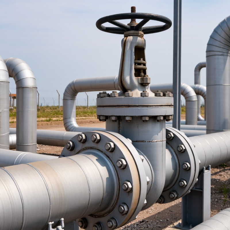
| Primary Leak Paths | The body-to-pipeline connection is a permanent welded joint, eliminating the external flange-and-gasket connection at that location. | Uses bolted flange joints with gaskets, which require correct gasket selection, bolt loading, alignment, and periodic inspection. | Welded and flanged end connections are covered by pipeline and valve design standards such as API 6D and ASME B16.34. |
| Structural Continuity | The valve can form a continuous welded section of the pipeline after qualified welding and inspection procedures are completed. | The bolted connection introduces a detachable joint between the valve and the adjoining pipe or equipment. | Joint design, welding procedure qualification, and examination should comply with the project piping code and applicable welding requirements. |
| External Leak Prevention | Fewer external joint interfaces reduce the number of potential gasket-related leakage points along the installed pipeline. | External sealing performance depends on gasket condition, flange-face condition, bolt preload, temperature, pressure, and installation quality. | External leakage control is influenced by design, materials, installation, and maintenance; no valve construction eliminates all possible leakage modes. |
| Pipeline Integrity | A properly welded valve connection avoids routine flange bolt loosening and reduces the risk of gasket relaxation caused by vibration or thermal cycling. | Bolted joints can be inspected, retightened, or disassembled, but they require controlled assembly and maintenance practices. | Pipeline integrity programs typically include welding control, non-destructive examination, pressure testing, and inspection records. |
| Installation Requirement | Requires qualified welders, approved welding procedures, suitable preheating or heat-treatment controls where applicable, and post-weld inspection. | Requires flange alignment, correct gasket installation, controlled bolt tightening, and verification of flange-face compatibility. | Requirements vary with material grade, wall thickness, service temperature, and the governing construction code. |
| Maintenance Access | Provides a permanent connection and is well suited to buried or restricted-access pipeline sections, but valve removal normally requires cutting and rewelding. | Allows comparatively easier removal for maintenance because the valve can be disconnected by unbolting the flanges. | Accessibility, isolation planning, and maintenance strategy should be considered during pipeline layout and valve selection. |
| Buried Pipeline Suitability | Commonly selected for buried pipeline sections because the welded connection has no exposed flange bolts or gasket cavity at the pipe interface. | May require additional protection, clearance, and access provisions for flanges, bolts, and gasket joints in buried or submerged applications. | Buried installation still requires coating, cathodic protection compatibility, weld inspection, and appropriate corrosion control. |
| Pressure and Temperature Selection | Available across recognized pressure classes and material combinations, subject to the valve manufacturer’s pressure-temperature rating and end-connection design. | Also available across recognized pressure classes, with the complete assembly limited by the lowest-rated component, including the flange and gasket. | ASME B16.34 provides pressure-temperature rating principles for many industrial valves; the project specification remains controlling. |
| End-Connection Standards | Butt-weld ends are commonly specified using dimensional requirements associated with ASME B16.25 and the applicable pipeline standard. | Flanged ends are commonly specified using standards such as ASME B16.5 or ASME B16.47, depending on nominal size and design requirements. | The selected valve end dimensions must match the adjoining pipe, flange standard, wall thickness, and project piping class. |
| Pressure Testing | Factory and site testing should verify shell integrity, seat performance, and the completed welded connection in accordance with the specified test standard. | Factory testing verifies the valve, while the installed flange joints require correct assembly and may need site leak testing under the project specification. | API 6D and ISO 5208 are commonly referenced for pipeline valve pressure and seat testing, subject to the purchase specification. |
| Fire-Safe Consideration | Welded construction can reduce external flange leakage exposure, but fire-safe performance still depends on the valve’s internal design, materials, and qualification. | Fire performance must consider both the valve design and the behavior of the external flange and gasket assembly during fire exposure. | API 607 and API 6FA are commonly used fire-test references for applicable industrial valves. |
| Best-Fit Applications | Long-distance transmission pipelines, buried lines, offshore or remote installations, and services where permanent high-integrity connections are preferred. | Above-ground facilities, stations, equipment skids, and locations where frequent valve removal or configuration changes are expected. | Final selection should consider safety, maintainability, installation method, isolation requirements, operating conditions, and lifecycle cost. |



 08045479132

 Send Inquiry


 Send Inquiry
 Send SMS