| Machine Definition | Turn-mill CNC machine | Combines turning and milling operations in one computer-controlled setup. | The workpiece can rotate for turning while driven tools perform milling, drilling, tapping, or other operations. |
| Primary Machining Processes | Turning, facing, boring, threading, milling, drilling, and tapping | Supports the production of cylindrical, prismatic, and multi-feature components with fewer setups. | The available processes depend on spindle configuration, tool capacity, machine axes, and control functions. |
| Machine Bed and Base | Rigid cast or fabricated base structure | Supports the moving assemblies and absorbs cutting forces, vibration, and thermal loads. | Often designed with wide guideway spacing, ribbing, and a low center of gravity for improved stiffness. |
| Main Spindle | Workholding spindle | Rotates the workpiece during turning and can index or position it for milling and drilling. | May use a chuck, collet, or hydraulic workholding system; speed range and torque are selected for the intended material and diameter. |
| Subspindle | Secondary workholding spindle | Transfers, supports, or machines the opposite end of a component. | Commonly used for back-end machining and reducing manual part repositioning; it is optional rather than universal. |
| Turret and Tool Stations | Indexing turret with static and driven tool positions | Holds cutting tools and indexes the required tool into the machining position. | Driven stations contain an auxiliary motor or mechanical drive for rotating milling cutters, drills, and taps. |
| Linear Axes | X, Y, and Z axes | Move the tool or workholding system to generate turning diameters, lengths, slots, holes, and other features. | Z generally follows the spindle centerline, X controls radial movement, and Y provides off-center movement on machines equipped with it. |
| Rotary Axes | C-axis and optional B-axis | Provide angular positioning or continuous interpolation for face milling, cross-drilling, and angled machining. | A C-axis controls spindle orientation; a B-axis tilts a tool or spindle head where multi-angle machining is required. |
| Guideways and Ballscrews | Linear guideways, box ways, and precision screws | Guide axis motion and convert motor rotation into controlled linear movement. | Guideway selection balances rapid movement, load capacity, damping, stiffness, and positioning accuracy. |
| CNC Control System | Controller, servo drives, motors, and feedback devices | Interprets the part program and synchronizes spindle speed, axis movement, tool changes, and auxiliary functions. | Encoder feedback enables closed-loop control of position and spindle orientation; interpolation coordinates several axes simultaneously. |
| Tool Management | Tool holders, offsets, and tool-monitoring functions | Maintains cutting geometry and helps the controller compensate for tool position and wear. | Tool offsets are measured or entered for geometry and wear; monitoring may detect overload, breakage, or abnormal cutting conditions. |
| Workholding | Chuck, collet, jaw, or bar-feeding arrangement | Secures the raw material while maintaining concentricity and resisting cutting forces. | The workholding method should match stock diameter, part length, material, required accuracy, and production volume. |
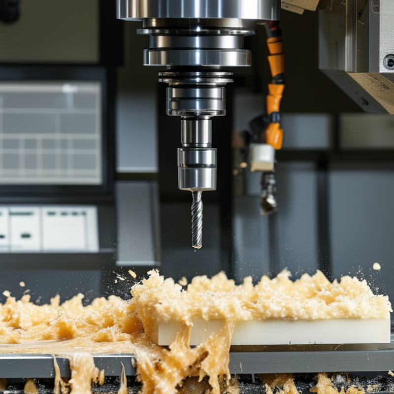
| Coolant and Chip Management | Coolant pump, nozzles, chip conveyor, and enclosure | Controls cutting temperature, lubricates the tool-workpiece interface, and removes chips from the work zone. | Flow direction and pressure should be suitable for the tool, material, chip shape, and machining operation. |
| Structural Layout | Horizontal or vertical configuration | Determines how the spindle, turret, chip flow, workholding, and operator access are arranged. | Horizontal layouts are common for bar and shaft work; vertical layouts can support large or heavy workpieces and favorable chip evacuation. |
| Typical Operating Sequence | Programming, setup, cutting, inspection, and correction | Coordinates all machining stages from raw stock preparation through finished-part verification. | A typical cycle includes workholding, tool setting, spindle synchronization, roughing, finishing, part transfer if required, and dimensional inspection. |
| Main Advantages | Fewer setups and broader machining capability | Improves positional consistency and can reduce handling, setup time, work-in-process, and floor-space requirements. | Best suited to complex parts that combine turned surfaces with cross-holes, flats, slots, keyways, threads, or angled features. |



 08045479132
 Send Inquiry

 Send Inquiry
 Send SMS