7 Tips for Choosing an FPC Stiffener Bonding Machine
Flexible circuits are compact, but stiffener bonding leaves little room for error. A crooked bond can affect component support, assembly fit, and downstream yield. The Fpc Stiffener Bonding Machine therefore deserves careful evaluation, not selection by speed claims alone. Consider bonding accuracy, pressure consistency, temperature control, fixture design, changeover time, and service support.
The market context matters. Prismark’s global PCB industry data put worldwide PCB production at roughly $73 billion in 2022, showing the scale of the manufacturing ecosystem behind these decisions. IPC’s North American PCB Statistical Program also tracks sales and bookings, useful indicators of changing production demand. Neither report ranks bonding machines. They do, however, remind buyers to assess equipment against real workloads, product mix, and capacity plans—not a single impressive demonstration.
PCB manufacturing authority Happy Holden is known for practical process-focused guidance. The following is an editorial paraphrase, not a verified verbatim quotation: “A stable process begins with control of the details.” Small errors matter. That principle fits stiffener bonding, where a slight shift in alignment or uneven pressure can show up clearly on a thin flex panel. This guide examines seven purchasing considerations, from repeatability and operator usability to qualification trials and supplier support. A useful caution: published specifications cannot replace testing with your own materials, stiffeners, and production settings. The best choice is the machine that performs reliably under those conditions.
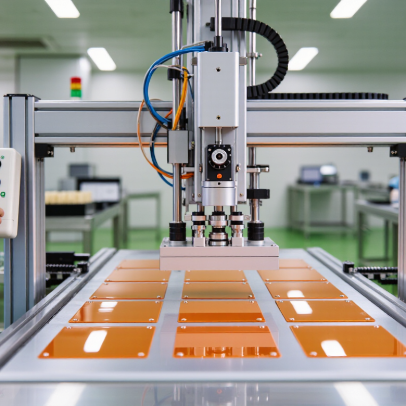
Map FPC Materials and Stiffener Types to IPC-2223 Design Rules
Map the FPC stack-up before comparing bonding machines. Polyimide flex circuits handle heat differently from thin PET constructions, and copper type can affect forming behavior. Identify the coverlay, adhesive, copper, and stiffener materials on the actual drawing. Then check the applicable IPC-2223 guidance for bend zones, layer transitions, and stiffened regions. Small details matter.
Stiffener choice changes both support and process demands. FR-4 provides firm local support, while polyimide can preserve a thinner, more flexible profile. Stainless steel may suit compact areas needing rigidity, but it adds weight and calls for careful edge control. Keep stiffeners out of dynamic bend areas unless the design specifically allows them. A bonding machine should offer stable temperature, pressure, and dwell-time control for the selected adhesive system. IPC-2223 informs the design; it does not provide a universal machine recipe.
Before purchase, test representative coupons using the real stack-up. Inspect adhesive squeeze-out, alignment, bubbles, and the transition between stiffened and flexible areas. Check results after cooling, not only while the part is under pressure. I have seen a setup look clean on a flat coupon, then show edge lift on a narrow production feature. That mismatch is easy to overlook. Record the settings and confirm them with repeat builds, since material lots and panel geometry can shift the process window.
Set Registration Accuracy with ±0.05 mm as a Buyer-Specified Target
7 Tips for Choosing an FPC Stiffener Bonding Machine
Registration accuracy deserves close attention when comparing FPC stiffener bonding machines. A buyer may specify ±0.05 mm as a target, but that figure is not a universal guarantee. Ask how the supplier defines registration, where it is measured, and under what conditions. Is the value based on one placement or repeated runs? Small shifts matter. A stiffener can look aligned at the edge yet drift near a fine-pitch feature. Request sample parts made with your actual FPC, stiffener, adhesive, and process settings.
Tip: Agree on a practical verification method before purchase. Check several parts across the panel, not just one convenient location. Record the vision system’s reference points, fixture condition, material flatness, and measurement tool. Then repeat the test after setup changes. These details make the ±0.05 mm target meaningful—and easier to troubleshoot.
Also review how the machine handles real production variation. Ask about calibration intervals, recipe storage, operator adjustments, and support for warped or flexible materials. A precise camera cannot correct a poorly seated fixture. Nor does a strong specification prove consistent results. I would leave room for doubt until trial runs confirm repeatability; it is easy to focus on the headline number and overlook everyday setup errors.
Check Platen Temperature Uniformity Against a ±2°C Control Target
When evaluating an FPC stiffener bonding machine, ask for a temperature map across the full platen, not just its center. A ±2°C control target is useful only when verified at several points under operating conditions. Place calibrated sensors near each corner and the center, then repeat the check after the platen stabilizes. Edge-to-center variation can soften adhesive unevenly, leaving a lifted corner or a visible squeeze-out line. Small gaps matter.
Measurement accuracy deserves attention too. ASTM E230/E230M specifies standard Type K thermocouple tolerance as ±2.2°C or ±0.75% of reading, whichever is greater. That tolerance can exceed a ±2°C uniformity target near typical bonding temperatures. Use a calibrated measurement system with tighter uncertainty, or the result may look precise without proving uniformity. IPC-6013E provides performance requirements for flexible printed boards, but a machine’s platen acceptance limit should still be confirmed in its own specification. Request the actual mapping data, sensor locations, setpoint, and stabilization time. A polished graph is not enough if it hides the edges.
Run a trial with the real stack-up, including the stiffener, adhesive, and release film. Record temperatures across the platen and inspect bonded samples for edge lift and inconsistent bond lines. I would also repeat the test after a production-length run; a cold-start result can be misleading. The process may drift, and operators sometimes trust the display too much. Check the surface, not only the screen.
Match Pressure and Dwell Time to the Adhesive Datasheet
Pressure and dwell time should come from the adhesive’s technical data sheet, not a machine’s default recipe. Check the specified temperature, pressure, dwell, and cure conditions together; changing one can alter the bond. For example, a fictional sheet might specify 0.2 MPa for 10 seconds at 150°C. Treat those figures as a starting point, not a universal FPC setting. Too much pressure can squeeze adhesive from beneath a stiffener. Too little may leave air pockets near its edges.
Record the actual platen temperature and pressure, then test samples made with the same copper, coverlay, stiffener, and adhesive stack. ASTM D3654/D3654M describes a shear-adhesion test method; it can help compare sample performance, but it does not prescribe a bonding-machine recipe. IPC-6013E provides qualification requirements for flexible printed boards, not adhesive-specific settings. Keep that distinction clear. A thermocouple near the bond area can reveal a slow heat-up that the machine display misses. I’d also inspect a few cross-sections. Honestly, that takes time, and it can expose uneven squeeze-out that a quick visual check misses. Adjust one process variable at a time, and document the result against the adhesive datasheet.
7 Tips for Choosing an FPC Stiffener Bonding Machine
Match Pressure and Dwell Time to the Adhesive Datasheet
The chart shows illustrative process settings, not universal specifications. Check the adhesive datasheet for its recommended pressure, dwell time, temperature, and test method. Choose a machine that can control these parameters consistently, then validate the settings on your FPC and stiffener materials.
Qualify Repeatability at Cpk ≥1.33 and Verify Parts per Hour
For an FPC stiffener bonding machine, a fast demonstration is not enough. Ask the supplier to run your actual flex circuits, adhesive, and stiffeners. Then qualify repeatability across multiple runs, not just a carefully prepared sample. A Cpk of at least 1.33 is a useful acceptance target when the process is stable and measurements are trustworthy. Check placement offset, bond position, and any critical dimensions against your drawing. Use calibrated gauges and agree on the sampling plan before testing. Small details matter.
A clean demo can mislead. Record results across shifts, material lots, and normal changeovers, then review the spread rather than relying on one average. If measurements cluster near a tolerance limit, investigate before accepting the machine. Cpk alone cannot prove the whole process is robust. Measure output too, using accepted parts per hour—not theoretical cycle speed. Include loading, alignment, inspection, and brief stoppages in the trial. Count rejected units separately. Ask operators to run the test themselves. Their handling may reveal awkward controls or setup steps that a technician misses. The trial takes time. It may also expose a problem you would rather find before installation.



 08045479132

 Send Inquiry


 Send Inquiry
 Send SMS