| 1. Confirm applicable standards | Specify the required standard and edition for the project and installation region. | Common references include IEC 60076 for power transformers and IEEE C57.12.00 for liquid-immersed distribution, power, and regulating transformers. Applicability depends on the equipment and jurisdiction. | A clear standard basis helps align design, testing, documentation, and acceptance requirements. |
| 2. Match the rating to the load | Review present demand, expected growth, load profile, ambient conditions, and any overload requirements. | For a balanced three-phase load, apparent power can be estimated as kVA = √3 × line voltage × line current ÷ 1,000. For example, 400 V and 100 A is approximately 69 kVA. | A suitable rating reduces the risk of persistent overloading while avoiding unnecessary oversizing. |
| 3. Verify voltage and connection details | Confirm primary and secondary line voltages, frequency, tap range, winding connection, phase displacement, and neutral requirements. | A specification might call for 11 kV primary, 400/230 V secondary, 50 Hz, and a stated vector group such as Dyn11. These are examples only; use the project’s system requirements. | Incorrect voltage or vector-group selection can prevent proper system connection or coordination. |
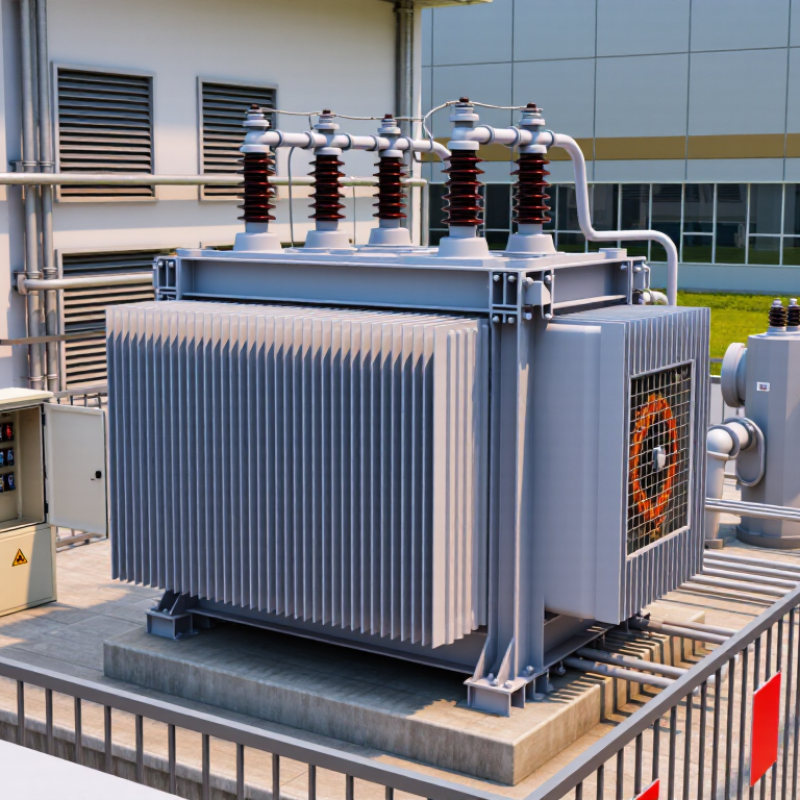
| 4. Choose the right enclosure and cooling arrangement | Decide between liquid-immersed and dry-type construction, then check indoor or outdoor suitability, cooling, ventilation, and environmental conditions. | Dry-type units are commonly considered for indoor installations; liquid-immersed units require suitable containment and spill or fire-risk provisions where applicable. Confirm the required enclosure rating for the actual location. | The installation environment affects safety measures, cooling performance, and long-term reliability. |
| 5. Plan installation space and access | Check equipment dimensions, cable entry and bending space, lifting route, foundation, ventilation, working clearances, and required separation from nearby equipment. | Use the manufacturer’s installation drawings and local electrical and building codes to set clearances; there is no single clearance suitable for every transformer. | Early layout checks can prevent access, cooling, cable-routing, and replacement problems. |
| 6. Review losses and impedance | Compare guaranteed no-load and load losses, impedance, temperature rise, and the required test or tolerance basis. | Ask for loss values in watts and impedance in percent at the specified rating and reference conditions. Evaluate energy cost over the expected operating profile. | Losses affect operating costs, while impedance influences voltage regulation and fault-current calculations. |
| 7. Make maintenance access part of the specification | Confirm access to terminals, tap changer, temperature indicators, fans or pumps, inspection points, and any sampling or draining points. | Request a maintenance-access drawing and a recommended inspection schedule. Keep routes and working areas clear in accordance with the equipment instructions and site rules. | Accessible service points make inspections and planned maintenance safer and easier to carry out. |



 08045479132

 Send Inquiry


 Send Inquiry
 Send SMS