| Water and sewer pipelines | Creates a structural sleeve around the carrier pipe where the utility passes beneath roads, railways, or other restricted areas. | Reduces the risk of damage from traffic loads, future excavation, ground movement, and contact with surrounding soil. | Jack-and-bore, guided boring, horizontal directional drilling, or open-cut installation. | Large enough to provide clearance around the carrier pipe; often supplied in welded steel sections for field joining. | Allow space for installation, alignment, carrier-pipe supports, drainage, and future maintenance access where required. |
| Gas distribution and transmission lines | Provides a protective barrier at selected crossings and helps maintain separation from transportation corridors and other utilities. | Limits damage from external impact, construction activity, and localized ground loading. | Trenchless boring or open-cut construction, subject to the project and regulatory requirements. | Carbon-steel casing with a diameter larger than the gas carrier pipe; the carrier is normally isolated from the casing. | Design must address corrosion control, electrical isolation, venting where required, and safe access for inspection. |
| Electrical power conduits | Encloses conduit banks or individual ducts and provides a robust route through areas exposed to heavy loading. | Protects conduits from crushing, impact, soil pressure, and accidental excavation. | Open cut, pipe jacking, auger boring, or horizontal directional drilling. | May use a single large casing for multiple conduits or separate casings for individual conduit groups. | Maintain required separation, heat dissipation, pulling tension limits, bend-radius requirements, and access for cable replacement. |
| Telecommunications and fiber-optic routes | Protects communication ducts and helps maintain a continuous pathway beneath roads, sidewalks, and rail lines. | Reduces the likelihood of duct deformation, impact damage, and service interruption caused by excavation or settlement. | Directional drilling, pipe jacking, microtunneling, or open-cut installation. | Typically sized to allow the duct assembly to be installed without excessive pulling force or sharp deflection. | Consider bend radius, pulling or bursting loads, water ingress, spare capacity, and detectable marker systems. |
| Road and highway crossings | Transfers external loads around a buried utility and provides a defined crossing beneath vehicle traffic. | Protects the carrier from pavement loads, road maintenance, resurfacing, and unplanned excavation. | Auger boring, jack-and-bore, pipe ramming, or open-cut installation. | Wall thickness and diameter are selected according to burial depth, soil conditions, construction loads, and crossing length. | Evaluate traffic loading, settlement, casing deflection, alignment tolerances, end seals, and drainage provisions. |
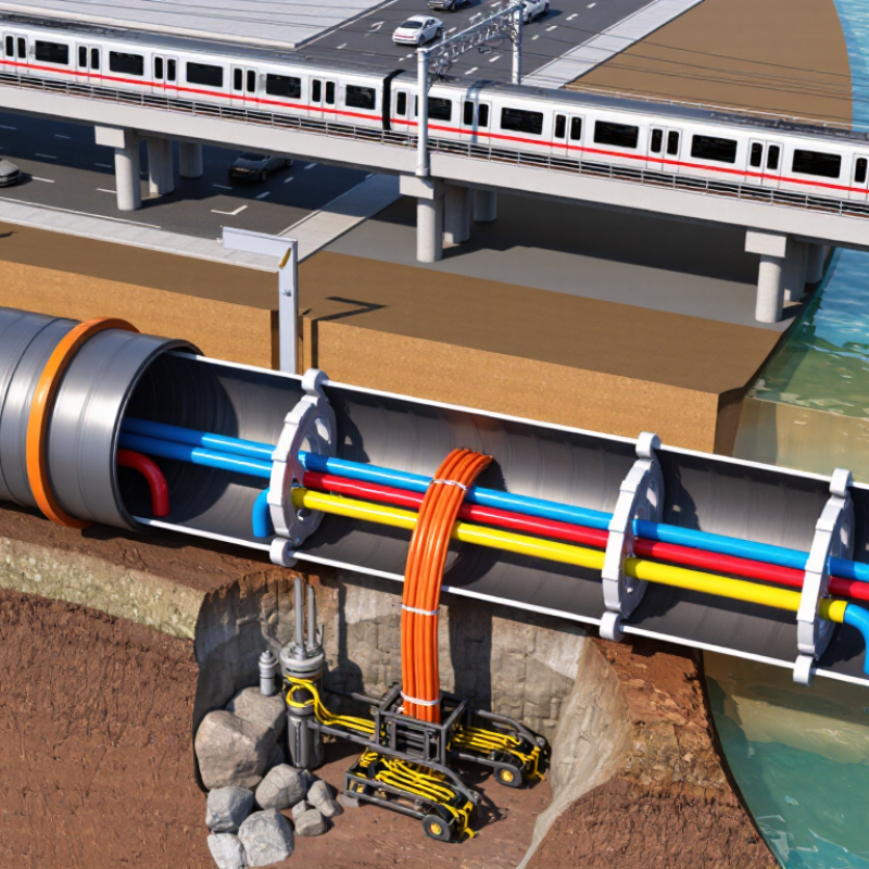
| Railway crossings | Forms a continuous protective tunnel that allows the utility to pass beneath the track structure with minimal surface disturbance. | Protects against heavy dynamic loads, vibration, maintenance work, and accidental contact with railway infrastructure. | Microtunneling, controlled boring, pipe jacking, or other approved trenchless methods. | Usually requires careful control of line, grade, settlement, and casing strength during installation. | Coordinate with the rail authority and assess vibration, allowable settlement, drainage, emergency access, and monitoring requirements. |
| Utility crossings beneath waterways | Provides a protective envelope for pipelines or conduits installed below rivers, channels, and drainage features. | Helps resist external impact, scour-related exposure, installation damage, and future channel maintenance activities. | Horizontal directional drilling, guided boring, or trenching with engineered backfill and protection. | May require increased wall thickness, external coating, concrete weight coating, or additional stabilization measures. | Assess scour depth, buoyancy, groundwater, hydraulic conditions, corrosion exposure, and environmental restrictions. |
| Vertical utility risers and shafts | Supports and shields a utility where it passes through foundations, slabs, retaining walls, or other structures. | Limits mechanical damage, abrasion, soil contact, and movement at structural penetrations. | Cast-in-place installation, core-drilled placement, excavation, or prefabricated structural assembly. | May include welded collars, sleeves, seals, or connection details designed for the surrounding structure. | Coordinate waterproofing, fire stopping where applicable, structural movement, corrosion protection, and pipe expansion. |
| Temporary construction protection | Acts as a sacrificial or removable sleeve while a carrier pipe, cable, or conduit is installed through an active work zone. | Protects utilities from construction equipment, temporary loads, rock contact, and unstable excavation conditions. | Open cut, temporary shoring systems, pipe ramming, or trenchless installation. | Selection is based on expected construction loads, duration, handling requirements, and whether removal is planned. | Inspect for deformation, provide secure end treatment, and confirm that the temporary casing does not restrict utility operation. |
| Abandoned or redundant utility protection | Can provide a stable enclosure for an existing utility that cannot be removed or is intended to remain isolated. | Reduces exposure to future excavation, settlement, corrosion-related debris, and accidental damage. | Open cut, slip-lining, localized excavation, or trenchless rehabilitation methods. | May use a new steel sleeve around the existing line, subject to access and clearance limitations. | Confirm ownership, isolation, residual contents, structural condition, groundwater control, and long-term corrosion behavior. |



 08045479132
 Send Inquiry

 Send Inquiry
 Send SMS