| 1. Feed throat | Guides material into the cutting chamber and helps limit access to moving cutters. | Check opening dimensions, material compatibility, guarding, and whether the throat suits the intended feed method. | Look for cracks, deformation, loose fasteners, and material buildup that could obstruct feeding. |
| 2. Interlock switch | Monitors an access guard or door and can prevent or stop hazardous operation when it is open, depending on the safety system design. | Confirm the switch is suitable for the machine’s safety circuit and that its status is clearly indicated to operators. | Test according to the manufacturer’s procedure; never bypass an interlock to keep the machine running. |
| 3. Feed hopper | Receives and directs bulk material toward the feed throat or cutting chamber. | Review capacity, loading access, wall construction, and compatibility with manual or conveyor feeding. | Check for damaged panels, worn liners, loose joints, and unsafe access points. |
| 4. Feed ram or pusher | Pushes material toward the cutters on machines designed for ram-assisted feeding. | Check ram force and travel against the intended material and confirm that guarding and controls suit the operating cycle. | Inspect guides, hydraulic hoses or drive components, and wear surfaces; follow lockout procedures before service. |
| 5. Access guard and guard latch | Separates operators from hazardous moving parts and provides a controlled access point for maintenance. | Verify that guards are robust, fit correctly, and cannot be opened unintentionally during operation. | Check hinges, latches, fasteners, and interlock alignment; do not operate with a damaged or unsecured guard. |
| 6. Emergency-stop device | Provides an accessible means to initiate an emergency stop when a hazardous condition occurs. | Check device location, visibility, accessibility, and integration with the machine’s control system. | Test as specified in the operating instructions and confirm the machine does not restart unexpectedly after reset. |
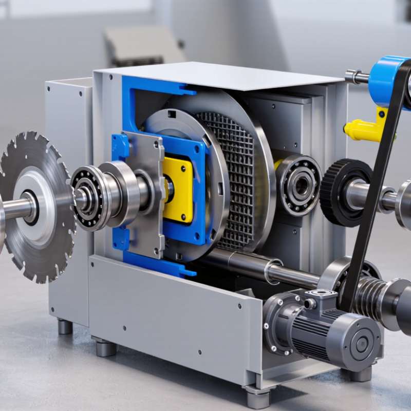
| 7. Cutter rotor or shaft | Carries and drives the cutting elements through the material. | Confirm the rotor configuration and working width match the machine duty and material type. | Check for abnormal vibration, damage, and bearing or alignment issues; maintenance requires isolation of energy sources. |
| 8. Cutting knives or cutters | Shear or tear incoming material into smaller pieces as the rotor turns. | Check cutter material, geometry, mounting arrangement, and availability of compatible replacements. | Inspect for wear, chipping, looseness, and uneven cutting; replace or rotate only as directed for the machine. |
| 9. Screen or sizing grid | Controls the approximate size of material that can pass through the cutting chamber. | Choose an opening size suitable for the required output and confirm the screen is compatible with the shredder design. | Check for blocked openings, cracks, and wear; clear or remove only after safe machine isolation. |
| 10. Drive motor and transmission | Supplies and transfers power to the cutting mechanism. | Compare rated power, supply requirements, duty cycle, and drive arrangement with the intended application. | Monitor unusual heat, noise, vibration, or leakage; use qualified personnel for electrical and transmission service. |



 08045479132

 Send Inquiry


 Send Inquiry
 Send SMS