| Definition | Mechanical flange | A flat or shaped mechanical connector used to join pipes, valves, pumps, equipment, or structural components. | It creates a detachable connection that can be opened for inspection, cleaning, repair, or replacement. |
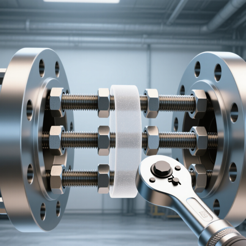
| How It Works | Bolted compression joint | Bolts clamp two flange faces together while a gasket fills surface irregularities and forms the seal. | The sealing force must remain sufficient for the internal pressure, temperature, and operating loads. |
| Main Components | Flange faces, bolts, nuts, washers, and gasket | The flange provides alignment and load transfer; fasteners provide clamping force; the gasket provides fluid sealing. | All components should be compatible with the piping material, fluid, pressure, temperature, and service environment. |
| Common Flange Types | Weld-neck, slip-on, socket-weld, threaded, lap-joint, and blind | Selection depends on pressure class, temperature, pipe size, material, installation method, and maintenance needs. | A blind flange closes a pipe end, while a lap-joint flange is useful where frequent dismantling is required. |
| Standards and Ratings | Nominal size, pressure class, facing, material, and dimensional standard | Typical systems specify nominal pipe size and pressure-temperature ratings, often using recognized piping standards. | Do not mix flange dimensions, bolt patterns, or pressure ratings unless compatibility has been verified. |
| Gasket Selection | Material, thickness, size, facing type, and service compatibility | Gaskets may be metallic, semi-metallic, compressed fiber, elastomeric, or graphite-based. | Use a new, undamaged gasket that is rated for the fluid, temperature, pressure, and flange surface finish. |
| Pre-Installation Inspection | Flange condition and alignment | Check for cracks, corrosion, damaged threads, burrs, distortion, contamination, and uneven or damaged sealing faces. | Pipe supports should prevent excessive external loads from being transferred to the flange joint. |
| Installation Sequence | Clean, align, install, tighten, and inspect | Clean the faces, center the gasket, insert compatible fasteners, and tighten gradually using a cross or star pattern. | Never use the bolts to force major pipe misalignment into position. |
| Bolt Tightening | Torque control and tightening pattern | Use the specified torque values and tighten in multiple passes, commonly from a low initial pass to the final specified torque. | Torque values vary with bolt size, lubricant, material, gasket type, and joint design; do not use a universal value. |
| Leak Testing | Pressure test or operational inspection | Test methods may include hydrostatic testing, pneumatic testing under controlled procedures, or approved leak-detection methods. | The joint must be depressurized and made safe before any tightening or repair work is attempted. |
| Routine Maintenance | Visual inspection and condition monitoring | Look for visible leakage, corrosion, gasket extrusion, loose fasteners, discoloration, vibration, and abnormal noise. | Inspection frequency should reflect service severity, operating history, regulatory requirements, and risk level. |
| Gasket Replacement | Replacement condition | Replace a gasket when the joint is opened, or when the gasket shows compression damage, cracking, swelling, erosion, or leakage. | Do not reuse most flange gaskets unless the applicable technical instructions specifically permit reuse. |
| Corrosion Control | External and crevice corrosion | Moisture, chemicals, temperature cycling, and contact between dissimilar metals can accelerate corrosion. | Use suitable materials, coatings, insulation practices, drainage, and inspection controls where required. |
| Safety Before Work | Isolation, depressurization, draining, and lockout | Isolate the system, release pressure, drain or purge hazardous contents, and apply the required lockout/tagout procedure. | Treat a flange as potentially pressurized until isolation and zero-energy status are verified. |
| Personal Protective Equipment | Minimum protective controls | Typical requirements include safety glasses, protective gloves, safety footwear, protective clothing, and additional equipment based on the hazard assessment. | Chemical, thermal, pressure, and confined-space hazards may require specialized PPE and procedures. |
| Common Failure Causes | Leakage, bolt failure, gasket damage, and flange distortion | Frequent causes include poor alignment, incorrect gasket selection, uneven tightening, vibration, thermal cycling, and excessive external loads. | Correct the underlying cause instead of repeatedly tightening the fasteners. |
| Good Practice | Documentation and verification | Record flange identification, gasket type, fastener condition, torque procedure, test results, inspection date, and corrective actions. | Follow applicable codes, site procedures, engineering specifications, and the component manufacturer's instructions. |



 08045479132
 Send Inquiry

 Send Inquiry
 Send SMS