| Electrical energy | Disconnect switch, circuit breaker, or other designated isolating device | Electrical lockout device compatible with the isolator, plus a personal safety padlock and tag | Confirm the device fits the specific switch or breaker and prevents operation. Follow the site procedure for identifying all electrical supplies. | A qualified person verifies absence of voltage with suitable test equipment after isolation and before work begins. |
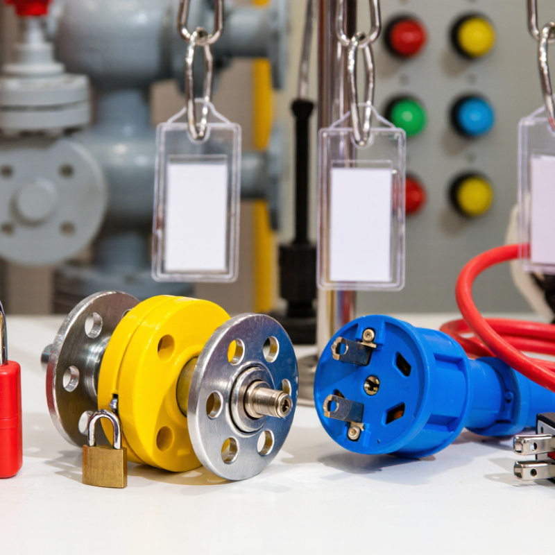
| Plug-connected electrical equipment | Power plug or receptacle connection | Plug lockout enclosure sized for the plug, secured with a personal safety padlock | Check that the enclosure fully contains the plug and cannot be removed while locked. Where required by the procedure, the plug must remain under the exclusive control of the worker. | Confirm the equipment cannot be energized and verify that stored electrical energy has been addressed. |
| Pneumatic energy | Compressed-air supply valve or designated isolation point | Valve lockout device appropriate to the valve, with a personal safety padlock and tag | Identify the correct supply valve and account for downstream pressure, accumulators, and any secondary air feeds. | Isolate the supply, release trapped pressure using the approved method, and verify that pressure is relieved. |
| Hydraulic energy | Hydraulic supply valve, pump disconnect, or designated isolation point | Compatible valve lockout device; additional blocking or restraint may be needed for moving parts | Consider pressure trapped in lines or accumulators and loads that could move when pressure is removed. Do not rely on a control valve alone if it does not isolate the energy source. | Relieve pressure as specified, check for stored energy, and secure components that could fall or move. |
| Mechanical or gravitational energy | Moving parts, raised equipment, counterweights, or suspended loads | Purpose-designed blocking, pins, or restraints; lockable isolators for any driving power source | Select a restraint rated and positioned for the load and expected forces. A lock on an energy switch does not by itself prevent gravity-driven movement. | Lower equipment where possible, or install and inspect suitable blocks or restraints before entering the hazard area. |
| Thermal energy | Steam, hot-fluid, or heating-system isolation valve; equipment power isolator where applicable | Compatible valve lockout device and personal safety padlock; use additional isolation where the procedure requires it | Identify supply and return lines, bypasses, and possible heat sources. Allow for cooling time and the risk of pressure or hot material remaining in the system. | Verify isolation and confirm the equipment or material has reached a safe condition using the site procedure. |
| Chemical or process energy | Process-line isolation valve, tank inlet, or other designated supply point | Valve lockout device and tag; additional measures such as line blanking may be required by the procedure | Check the substance, line configuration, possible cross-connections, and whether a closed valve provides adequate isolation for the task. | Drain, flush, purge, or test the system as required by the chemical hazard assessment and site procedure. |



 08045479132
 Send Inquiry

 Send Inquiry
 Send SMS