| Rated Capacity | Select a transformer that covers the calculated maximum demand plus future growth. | 100–2,500 kVA for common compact distribution applications. | Prevents overheating, nuisance tripping, and premature insulation aging. | Target operating load at approximately 70–85% of nameplate capacity under normal peak conditions. |
| Load Growth Allowance | Include expected expansion, additional equipment, and changes in operating schedules. | Common planning margin: 15–25% above present calculated demand. | Reduces the likelihood of an early transformer replacement or costly site modification. | Document present load, forecast load, motor starting demand, and non-linear loads. |
| Primary Voltage | Match the utility or incoming medium-voltage system. | Typical distribution levels include 6.6 kV, 10 kV, 11 kV, 13.8 kV, and 20 kV. | Incorrect voltage selection can make the equipment unsafe or incompatible with the network. | Confirm nominal voltage, highest system voltage, frequency, and utility fault level. |
| Secondary Voltage | Match the voltage required by the site's distribution boards and end-use equipment. | Common low-voltage outputs include 400/230 V or 415/240 V, three-phase, four-wire. | Ensures correct equipment operation and limits voltage conversion losses. | Verify phase arrangement, neutral requirements, grounding method, and permissible voltage tolerance. |
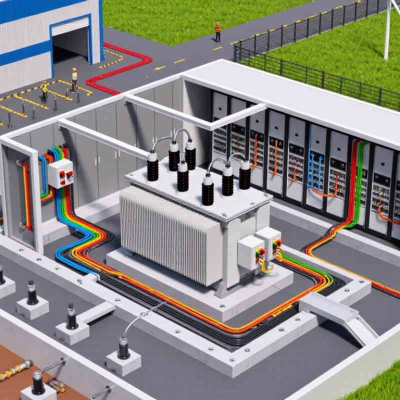
| Installation Location | Choose indoor, outdoor, or semi-outdoor construction according to exposure and access conditions. | Outdoor enclosures commonly use an ingress protection rating of IP54 or higher, subject to the site environment. | Protects energized parts from water, dust, accidental contact, and environmental damage. | Assess rain, dust, salt spray, corrosive gases, solar radiation, and flooding risk. |
| Available Footprint | Allow room for ventilation, cable bending, inspection, maintenance, and safe working clearances. | A compact package may occupy roughly 3–12 m², depending on rating and switchgear arrangement. | A small footprint is useful only if operators can safely access and service the equipment. | Confirm layout drawings, door swing, emergency access, cable routes, and local clearance rules. |
| Ambient Temperature | Use the manufacturer's rated ambient range and apply derating where necessary. | Many standard designs are based on a maximum ambient temperature near 40°C, subject to the applicable standard. | High temperature reduces permissible loading and accelerates thermal aging. | Check maximum, minimum, daily average, altitude, ventilation, and solar heat gain. |
| Cooling Method | Select natural air cooling or liquid cooling based on capacity, noise, fire risk, and maintenance needs. | Dry-type transformers are often used indoors; liquid-immersed units are common where higher capacity or outdoor installation is required. | Cooling affects efficiency, enclosure design, fire protection, and service intervals. | Evaluate heat dissipation, ventilation openings, liquid containment, and local fire regulations. |
| Short-Circuit Withstand | The assembly must withstand the prospective fault current at the installation point. | Low-voltage switchboards may be specified with short-circuit ratings such as 25 kA or 50 kA for a defined duration, subject to system calculations. | Adequate withstand capability limits equipment damage and arc-fault consequences. | Obtain the utility fault-current figure and coordinate protective-device ratings. |
| Protection Functions | Provide protection against overload, short circuit, earth fault, overtemperature, and abnormal voltage where applicable. | Typical equipment includes medium-voltage fuses or circuit breakers, low-voltage main breakers, and temperature monitoring. | Coordinated protection isolates faults while maintaining service to unaffected circuits. | Review selectivity, relay settings, backup protection, and emergency shutdown arrangements. |
| Grounding and Bonding | Bond all exposed conductive parts and design the earth system according to fault-current and touch-voltage calculations. | The installation normally includes an earth grid or electrode system, protective bonding conductor, and neutral grounding arrangement. | Reduces electric-shock risk and provides a controlled path for fault current. | Verify soil resistivity, earth resistance targets, step and touch voltage, and testing access. |
| Safety Interlocking | Prevent unsafe switching, access to live compartments, and opening of doors under hazardous conditions. | Common features include key or mechanical interlocks, door locks, shutters, earthing switches, and position indicators. | Interlocks reduce the risk of incorrect operation and accidental contact with energized components. | Confirm the switching sequence and test each interlock during commissioning. |
| Applicable Standards | Use the standards required by the project jurisdiction, utility, and authority having jurisdiction. | Common references include IEC 62271 for high-voltage switchgear, IEC 60076 for power transformers, IEC 61439 for low-voltage assemblies, and IEEE C57 series where applicable. | Standards define design, testing, insulation, temperature-rise, fault withstand, and operational requirements. | Request routine-test reports, type-test evidence where required, drawings, and conformity documentation. |
| Noise Level | Meet building, occupational, and environmental noise limits at the site boundary or occupied areas. | Transformer sound levels commonly fall near 50–70 dB(A), depending on rating, cooling, and measurement conditions. | Noise can affect offices, residences, hospitals, and other sensitive locations. | Obtain guaranteed sound data and evaluate barriers, vibration isolation, and operating load. |
| Maintenance Access | Provide safe access for inspection, testing, cable termination, replacement, and cleaning. | Front-access designs can reduce room depth; rear access may still be required for certain cable and transformer arrangements. | Poor access increases outage duration and creates additional worker-safety hazards. | Review maintenance intervals, lifting points, spare-part requirements, and safe isolation procedures. |
| Fire and Spill Protection | Provide fire separation, detection, suppression, and liquid containment when required by the installation type. | Liquid-filled units may require a bund or containment volume sized according to local code and environmental risk assessment. | Limits fire spread and prevents insulating liquid from entering soil or drainage systems. | Check liquid type, fire point, spill pathway, drainage, separation distance, and emergency response plan. |



 08045479132
 Send Inquiry

 Send Inquiry
 Send SMS