| 1 | Review the CAD Design | The part drawing is examined for dimensions, tolerances, threads, grooves, radii, chamfers, and surface-finish requirements. | The machinist identifies turning features and confirms which surfaces can be produced by rotating the workpiece. | Dimensional tolerances commonly range from approximately ±0.01 to ±0.10 mm, depending on the design and process. | A complete process plan and an approved engineering drawing. |
| 2 | Select the Raw Material | A cylindrical bar, tube, or prepared blank is selected with sufficient allowance for machining. | The material is checked for diameter, length, grade, straightness, and visible defects before loading. | Common materials include steel, stainless steel, aluminum, brass, copper, titanium, and engineering plastics. | Correct material certification and an appropriate stock allowance. |
| 3 | Prepare the CNC Program | The design is converted into toolpaths and machine instructions, usually using computer-aided manufacturing software. | The program defines spindle speed, feed rate, cutting depth, tool changes, coolant commands, and work offsets. | Programming may use metric or imperial units; cutting values depend on material, tooling, and machine capability. | A verified numerical-control program with no toolpath collisions. |
| 4 | Set Up the Workholding | The raw stock is secured so that it rotates concentrically and remains stable during cutting. | A three-jaw chuck, collet, soft jaws, or other suitable fixture holds the workpiece. | Runout is checked with a dial indicator; the acceptable value depends on the required part accuracy. | Secure clamping, correct protrusion, and controlled radial runout. |
| 5 | Install and Measure Cutting Tools | Turning inserts, drills, boring bars, grooving tools, or threading tools are installed in the turret. | Tool geometry, insert condition, tool number, length offset, and radius compensation are entered or measured. | Insert geometry and grade are selected according to material, cutting load, and required surface finish. | Correct tool offsets and sharp, undamaged cutting edges. |
| 6 | Set Work Coordinate and Dry Run | The machine establishes the workpiece zero point and checks the programmed motion before cutting material. | The operator touches off tools, sets the work offset, verifies clearance, and performs a simulation or single-block run. | Clearance is verified at rapid-traverse positions and near the chuck, jaws, tailstock, and finished surfaces. | Confirmed origin, safe tool motion, and correct machining sequence. |
| 7 | Face the Workpiece | Material is removed from the end of the stock to create a flat reference surface. | A facing tool moves radially across the rotating end face. | Feed and speed are selected according to workpiece diameter, material, insert geometry, and machine limits. | Flat end face and a reliable axial reference for subsequent operations. |
| 8 | Perform Rough Turning | Large amounts of material are removed quickly to approach the required external profile. | The tool travels along the workpiece axis while the spindle rotates the stock. | A machining allowance is intentionally left for finishing; cutting depth depends on material and machine rigidity. | Efficient stock removal without excessive vibration, heat, or tool wear. |
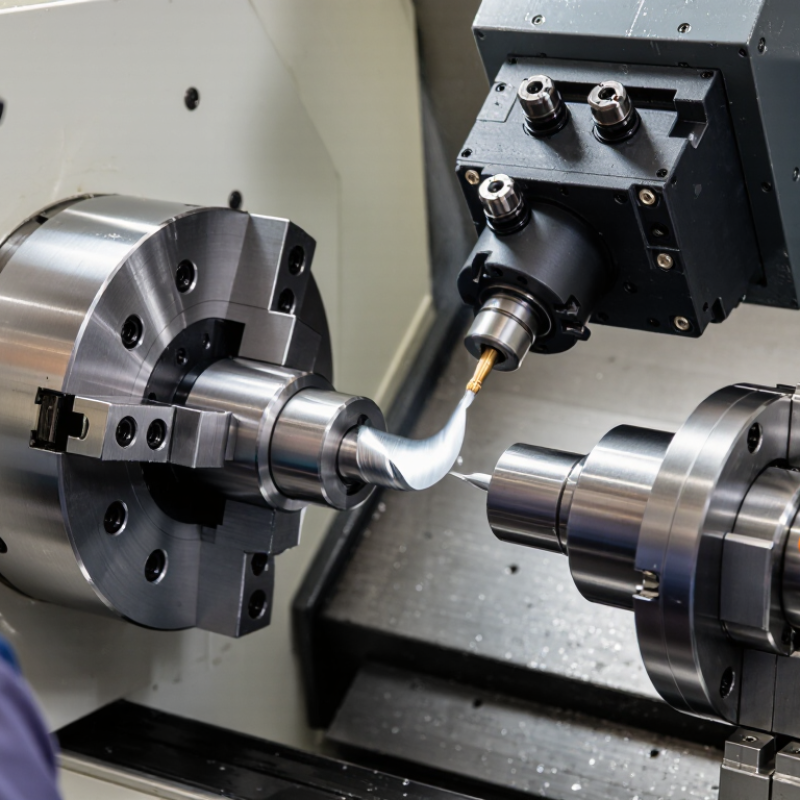
| 9 | Machine Special Features | Additional operations create holes, bores, grooves, tapers, radii, chamfers, or external and internal threads. | Live tooling, drills, boring bars, grooving tools, and threading tools may be used, depending on the lathe configuration. | Thread pitch, bore diameter, groove width, and taper angle are programmed from the drawing. | Accurate functional features that match the specified geometry. |
| 10 | Perform Finish Turning | A smaller final cut removes the remaining allowance and produces the required dimensions and surface quality. | The finishing tool follows the final contour at a controlled feed rate. | Surface roughness may be specified as Ra; achievable values depend on tool nose radius, feed, material, and machine stability. | Final profile, diameter, length, and surface finish. |
| 11 | Apply Coolant and Manage Chips | Cutting fluid may reduce heat, improve tool life, flush chips, and support consistent surface quality. | Flood coolant, through-tool coolant, air, or dry machining is selected according to the material and operation. | Coolant concentration and flow must follow the process requirements and safety procedures. | Controlled cutting temperature, manageable chips, and reduced risk of chip recutting. |
| 12 | Inspect the Finished Part | The completed part is checked against the drawing and process specifications. | Calipers, micrometers, gauges, thread gauges, height gauges, or coordinate-measuring equipment may be used. | Inspection frequency and instrument resolution are selected according to tolerance and quality requirements. | Accepted dimensions, surface finish, threads, burr condition, and overall conformity. |
| 13 | Deburr and Complete the Part | Sharp edges and machining residues are removed, and any specified cleaning or protective treatment is completed. | Manual deburring, brushing, washing, polishing, or other approved finishing methods may be applied. | Edge-break size and final treatment are controlled by the technical drawing or inspection standard. | Clean, safe-to-handle parts ready for assembly, packaging, or further processing. |



 08045479132
 Send Inquiry

 Send Inquiry
 Send SMS