| Batch Fixed-Bed Reactor | Intermittent loading, heating, cooling, and unloading | Approximately 5–20 tonnes per batch | 8–16 hours per cycle, depending on feed size and heating rate | Approximately 400–500°C | Simple layout; comparatively low initial investment; suitable for small-scale operations; easy to inspect and maintain | Lower productivity; more manual handling; repeated heating and cooling can reduce energy efficiency; production is not continuous | Small plants, pilot projects, variable feedstock, and markets with limited daily tyre supply |
| Semi-Continuous Reactor | Multiple reactors or staged operation with alternating loading and discharge | Approximately 10–30 tonnes per day | Typically 6–12 hours in the reaction zone | Approximately 400–500°C | Better utilization of heating and condensation equipment than a single batch unit; more regular output; moderate capital requirement | More complex controls and material handling; still requires periodic interruption or reactor switching | Medium-sized facilities requiring a balance between investment, flexibility, and operating continuity |
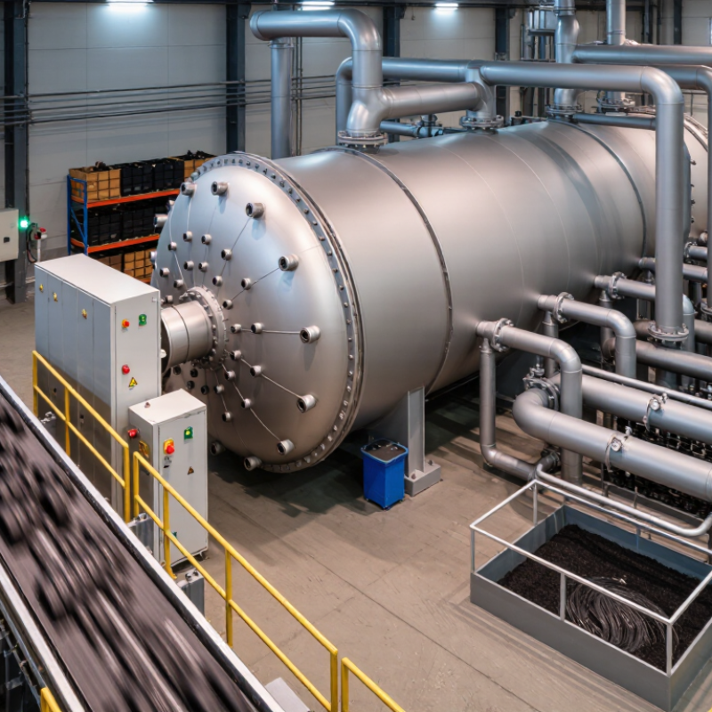
| Continuous Rotary Kiln | Continuous feeding and continuous discharge through a slowly rotating cylindrical reactor | Approximately 20–100 tonnes per day, depending on reactor dimensions and feed preparation | Usually 30–120 minutes in the heated section | Approximately 400–550°C | High throughput; continuous production; good tolerance for shredded tyres and rubber-rich feed; easier integration with automatic feeding and carbon discharge | Higher capital and maintenance requirements; sealing, refractory lining, and temperature uniformity require careful engineering | Commercial plants with stable feedstock supply and a need for consistent daily production |
| Continuous Screw or Auger Reactor | A screw conveys prepared tyre material through a heated, oxygen-limited chamber | Approximately 5–50 tonnes per day, depending on screw diameter and feed properties | Generally several minutes to less than 1 hour | Approximately 450–600°C | Compact footprint; accurate solids conveying; rapid heat transfer when feed is properly sized; well suited to automated operation | Sensitive to feed size, moisture, and metal contamination; screw wear can be significant; may require extensive pretreatment | Facilities using consistently shredded or granulated tyre feed and seeking a compact continuous system |
| Vacuum Pyrolysis Reactor | Thermal decomposition under reduced pressure and limited oxygen exposure | Commonly small to medium scale; capacity varies substantially by reactor design | Often shorter than conventional batch operation, depending on pressure and feed size | Approximately 350–500°C | Reduced oxygen contact; potentially improved control of vapour residence time; may help limit secondary cracking reactions | Requires vacuum pumps, reliable seals, and additional process control; higher technical complexity and maintenance needs | Projects prioritizing controlled vapour processing, research, or specialized product-quality targets |
| Catalytic Pyrolysis System | Thermal decomposition combined with a catalyst in the reactor or downstream vapour phase | Capacity depends on the base reactor; commonly small to medium scale for controlled operation | Usually shorter vapour residence time than non-catalytic systems | Often approximately 350–500°C, depending on catalyst type and process objective | Can alter vapour composition and promote lighter hydrocarbon fractions; may improve control over selected product characteristics | Catalyst deactivation, regeneration, contamination, and replacement add operating complexity and cost; results are feedstock-specific | Facilities with technical staff, consistent feedstock, and a defined need for modified liquid or gas properties |



 08045479132
 Send Inquiry


 Send Inquiry
 Send SMS