| Heat-shrink butt splice | Joining two in-line conductors in repair, control, and low-voltage wiring. | Common bands include 0.5–1.0 mm² (approximately 22–18 AWG), 1.5–2.5 mm² (approximately 16–14 AWG), and 4–6 mm² (approximately 12–10 AWG). | Both conductors must fit the barrel’s specified range; use a splice designed for the conductor material and stranding. | IEC 60352-2 is relevant to solderless crimped connections. Check the exact product documentation for any applicable UL or regional certification. | Confirm the finished splice diameter and heat-shrink recovery range fit the wire insulation and installation space. |
| Heat-shrink ring terminal | Securing a conductor to a stud or screw connection point. | Available across multiple wire-size bands, commonly including 0.5–1.0, 1.5–2.5, and 4–6 mm². | Match the stud-hole diameter to the fastener; common metric sizes include M3, M4, M5, and M6, but availability varies. | Verify crimp performance and any required terminal approvals for the intended equipment and market. | Choose a ring size that fits the fastener without excessive clearance; consider vibration and access for installation. |
| Heat-shrink fork (spade) terminal | Connecting a wire to a screw or stud where a slotted terminal can simplify removal. | Commonly offered in several ranges, including 0.5–1.0, 1.5–2.5, and 4–6 mm². | Check stud size, fork width, and whether the terminal can remain secure under the expected movement or vibration. | IEC 60352-2 may inform crimp-connection evaluation; confirm product-specific listings and application requirements. | Use a ring terminal instead where the connection must not be removable without fully taking off the fastener. |
| Heat-shrink female quick-disconnect terminal | Removable connections to compatible male blade tabs in appliances, vehicles, and control panels. | Wire ranges vary by barrel design; common versions cover 0.5–1.0, 1.5–2.5, or 4–6 mm². | Match the mating tab width and thickness. Common tab widths include 2.8, 4.8, and 6.3 mm; verify the actual tab specification. | Confirm the terminal’s intended current, temperature, and environmental ratings from its technical documentation. | Check retention force and available clearance around the mating tab; dimensions are not interchangeable just because widths are similar. |
| Heat-shrink male quick-disconnect terminal | Providing a blade connection that mates with a compatible female quick-disconnect. | Offered in multiple conductor ranges, often aligned with common 0.5–1.0, 1.5–2.5, and 4–6 mm² bands. | Match blade width and thickness to the female terminal; use compatible mating components from the same dimensional system. | Check the applicable product standard or certification for the finished connection and destination market. | Confirm blade geometry and fit before installation; a loose or overly tight mating connection can cause unreliable contact. |
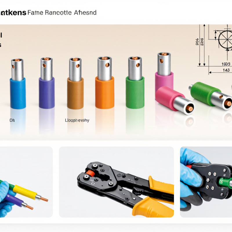
| Heat-shrink bullet connector | Compact, separable wire-to-wire connections in vehicle and equipment wiring. | Size ranges depend on the bullet diameter and crimp barrel; select by the stated conductor range. | Male and female halves must match in diameter, length, and locking or retention design. | For crimp quality, consult IEC 60352-2 and the connector manufacturer’s application instructions where applicable. | Check whether the connected pair can be disconnected after the heat-shrink sleeves have been recovered. |
| Heat-shrink step-down butt splice | Joining conductors of different sizes, such as a larger supply wire to a smaller branch wire. | Each end has a separate specified conductor range; combinations vary by product. | Confirm the larger and smaller conductors are inserted into the correct ends and fall within their respective ranges. | Verify crimp instructions, conductor-material compatibility, and any required product certification. | Do not substitute for a splice rated for the circuit’s current, temperature, or environmental conditions. |
| Heat-shrink parallel splice | Branching or joining conductors side-by-side where a compatible parallel-crimp design is specified. | Ranges and the number of conductors supported are design-specific; follow the stated combination table. | Check total conductor area, conductor count, and the specified crimp tool and die. | Confirm that the connector’s documented test or approval scope covers the intended wire combination. | A standard butt splice is not automatically suitable for multiple conductors in one barrel. |
| Heat-shrink flag quick-disconnect terminal | Connections in tight spaces where the wire exits at an angle to the mating tab. | Available for multiple wire-size bands; select by both barrel range and mating-tab dimensions. | Check tab width and thickness, wire exit direction, and clearance for the insulated sleeve. | Review the product’s application ratings and any required regional conformity documentation. | Useful where a straight disconnect would bend the wire sharply or interfere with nearby parts. |
| Heat-shrink pin terminal | Terminating a stranded wire for insertion into a compatible terminal block or connector system. | Pin diameter and conductor range are product-specific; select from the terminal-block manufacturer’s accepted dimensions. | Confirm pin length, diameter, insertion depth, and compatibility with the clamping mechanism. | Check the terminal block’s specifications and the pin terminal’s documented crimp requirements. | Do not assume a pin terminal is interchangeable with a bootlace ferrule; their geometries and intended connections differ. |



 08045479132

 Send Inquiry


 Send Inquiry
 Send SMS