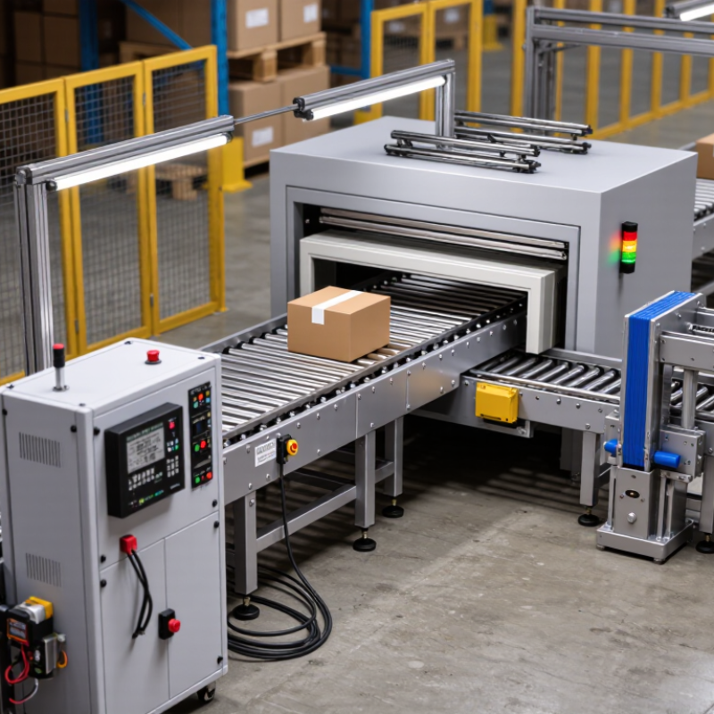
| Basic definition | An automatic diverter is a powered mechanism that redirects products, packages, materials, or process flow from a primary route to one or more alternative routes. | A controller receives a routing command, activates an actuator, and moves a gate, arm, belt, roller, flap, or valve into the required position. | The exact design depends on whether the system handles solid products, bulk material, air, liquid, or gas. |
| Primary purpose | To automatically sort, separate, reject, bypass, merge, or redirect material without continuous manual intervention. | Sensors or an upstream control system identify the item or process condition and send a destination signal to the diverter. | Correct routing logic is essential; an incorrect signal can send material to the wrong destination. |
| Common actuation methods | Electric motor, pneumatic cylinder, hydraulic cylinder, solenoid, or electromechanical linear actuator. | The actuator converts an electrical or fluid-power command into mechanical movement. | Pneumatic systems require clean, dry air; electric systems require suitable power, control, and protection. |
| Typical sensing devices | Photoelectric sensors, proximity sensors, barcode readers, vision systems, encoders, pressure sensors, flow meters, or level switches. | The sensor detects position, identity, quantity, pressure, flow, or level and transmits information to a PLC or dedicated controller. | Sensor alignment, cleanliness, and correct calibration directly affect routing accuracy. |
| Typical control sequence | Detect or identify → calculate destination → confirm timing → actuate → verify position → return or hold. | The controller coordinates the diverter with conveyor speed, spacing, flow conditions, and downstream availability. | A position feedback signal is preferable where a failed or incomplete movement could cause blockage or unsafe conditions. |
| Common mechanical forms | Pivoting arm, pop-up wheel, swing gate, sliding gate, belt steer, roller transfer, chute flap, rotary valve, or pipeline diverter valve. | Each form changes the direction or path of the material using a controlled movement suited to the application. | The mechanism must match product shape, mass, fragility, temperature, abrasiveness, and required throughput. |
| Response and cycle behavior | Response time and cycle rate vary widely by actuator, travel distance, load, control logic, and product spacing; no single universal speed applies. | The controller must move the diverter fully into position before the target item or process flow reaches the decision point. | Manufacturers’ cycle ratings should be checked against actual load, duty cycle, acceleration, and stopping requirements. |
| Main benefits | Reduced manual handling, repeatable routing, faster sorting, improved process integration, better traceability, and more flexible line configuration. | Automation links detection, decision-making, actuation, and feedback into a repeatable sequence. | Benefits are greatest when product presentation, sensor data, and downstream capacity are consistent. |
| Key limitations | Initial cost, control-system complexity, sensor dependency, wear of moving parts, noise, energy use, and possible downtime during faults. | The diverter relies on coordinated mechanical, electrical, software, and sometimes pneumatic or hydraulic components. | Poorly defined product tolerances or unstable flow conditions can reduce accuracy and increase jams. |
| Installation requirements | Adequate structural support, access for maintenance, correct alignment, compatible utilities, guarding, sensors, controls, and safe discharge areas. | The diverter is installed at a calculated decision point and integrated with upstream and downstream equipment. | Allow clearance for actuator travel, cleaning, inspection, emergency access, and removal of worn components. |
| Routine maintenance | Inspect fasteners, hinges, bearings, belts, rollers, seals, guides, wiring, tubing, sensors, guards, and actuator mounting points. | Regular inspection identifies wear, looseness, contamination, leakage, misalignment, and abnormal noise before failure occurs. | Use the equipment manufacturer’s lubrication type, inspection intervals, and replacement criteria. |
| Cleaning and contamination control | Remove accumulated dust, product residue, debris, moisture, and foreign objects from moving and sensing areas. | Clean surfaces allow free movement and help sensors detect products or positions reliably. | Cleaning methods must be compatible with electrical enclosures, seals, lubricants, and the material being handled. |
| Frequent fault causes | Blocked travel, product jams, incorrect timing, sensor contamination, loose connections, air leaks, worn bearings, or failed position feedback. | A fault may prevent movement, cause an incomplete stroke, or produce an incorrect route decision. | Troubleshooting should begin with isolation and safety checks, followed by mechanical, utility, sensor, and control-system checks. |
| Safety considerations | Physical guarding, emergency stops, interlocks, lockout/tagout procedures, pinch-point controls, and safe access are commonly required. | Safety systems stop or inhibit hazardous motion when a guard is opened, an emergency stop is activated, or a dangerous condition is detected. | The installation should be assessed against applicable local machinery, electrical, and workplace safety requirements. |
| Selection criteria | Material characteristics, load, dimensions, throughput, route count, accuracy, available utilities, environmental conditions, cleanability, and control integration. | The selected diverter must provide sufficient force, travel, response, durability, and control compatibility for the complete operating cycle. | Testing with representative products and operating conditions is recommended before final installation. |



 08045479132

 Send Inquiry


 Send Inquiry
 Send SMS