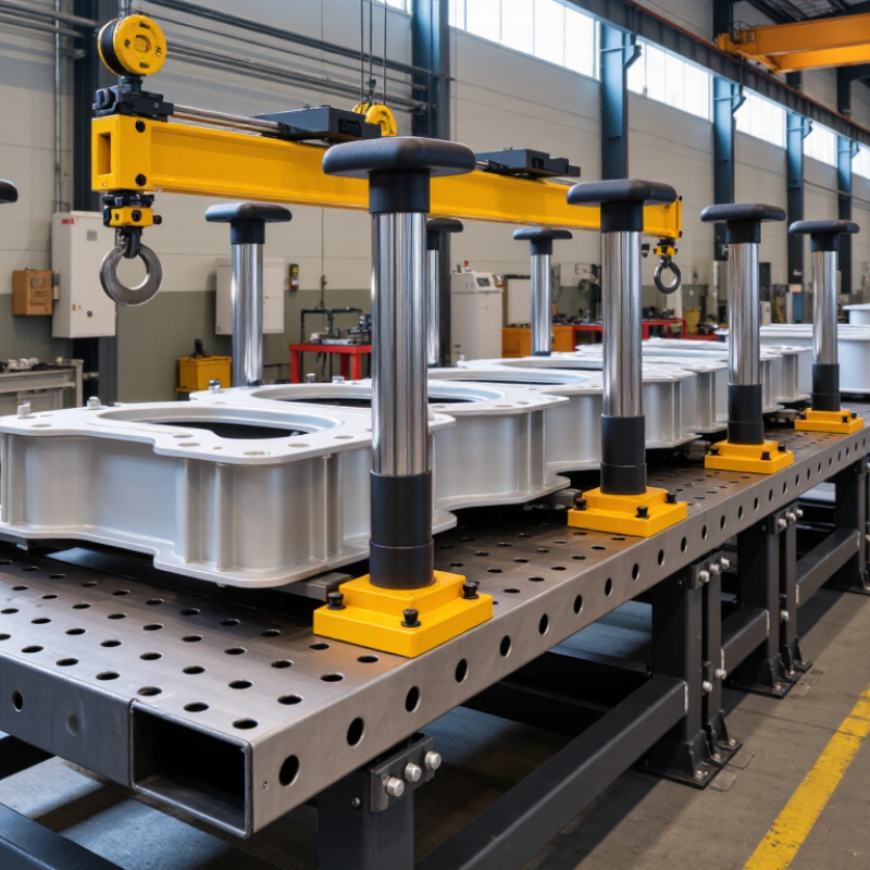
| 1. Main support area | Rigid frame, level work surface, replaceable protective pads | Provides a stable base for assembly and supports the transformer body during fitting and inspection. | Keep the surface level and clean. Use smooth, non-abrasive contact surfaces to help protect the thin amorphous core material from scratches and localized impact. |
| 2. Core positioning area | Core support blocks, locating stops, adjustable guides, padded clamps | Holds the core in its intended position while the body is assembled. | Arrange supports to suit the core shape and approved assembly method. Apply only the restraint needed to prevent movement; avoid concentrated pressure that could deform or damage the core. |
| 3. Winding and coil area | Coil supports, centering guides, insulated separators | Supports and aligns windings as they are fitted around or alongside the core, according to the transformer design. | Provide clear access for careful placement. Keep winding edges and leads clear of sharp corners, and use separators where required by the design and insulation system. |
| 4. Insulation and small-parts area | Organized trays, insulation-sheet holders, fastener bins, component labels | Stores insulation materials and assembly hardware close to the point of use. | Separate parts by type and assembly step. Protect insulation from moisture, dust, oil, and accidental creasing; keep loose hardware away from the core and windings. |
| 5. Handling and lifting area | Clear lifting access, rated hoist or lifting aid where needed, designated staging space | Allows heavy or awkward components to be moved into position without relying on uncontrolled manual handling. | Plan the lifting path before assembly. Use lifting equipment and attachments rated for the load, and keep the operator’s view and access to the work area unobstructed. |
| 6. Tools and fastening area | Tool holders, torque-controlled tools where specified, fastener bins | Keeps assembly tools accessible for joining structural parts and completing specified mechanical connections. | Store tools in assigned locations and follow the assembly drawing or work instruction for fastening sequence and torque. Do not place tools on exposed core or winding surfaces. |
| 7. Inspection and electrical-test area | Inspection access, measurement tools, test-point access as specified | Supports checks of alignment, clearances, connections, and other requirements in the production documentation. | Keep inspection points visible and accessible. Electrical tests should be performed only with the specified equipment and safety procedures, by qualified personnel. |
| 8. Operator and material-flow area | Operator access, incoming-part staging, completed-assembly staging | Organizes the sequence from prepared parts to assembled transformer body and reduces unnecessary handling. | Place frequently used parts within comfortable reach while preserving a clear walkway. Keep incoming and completed items separated to reduce mix-ups and prevent accidental contact damage. |



 08045479132

 Send Inquiry


 Send Inquiry
 Send SMS